Deploy Snipe It with Kubernetes

Deploy Snipe It with Kubernetes

In the previous post, we spoke about Snipe It and how to deploy it with docker. As is a simple product let’s introduce how to deploy this simple tool with Kubernetes.

First let’s introduce Kubernetes.

Kubernetes is an open-source platform for managing containerized workloads and services. Kubernetes manage containers system resiliently. It takes care of scaling and failover for your application, provides deployment patterns, and more.

Kubernetes works with several components:

Kubernetes is deployed with a Cluster who consists of a set of worker machines, called nodes, that run containerized applications. Every cluster has at least one worker node.

The worker node(s) host the Pods that are the components of the application workload. The control plane manages the worker nodes and the Pods in the cluster. In production environments, the control plane usually runs across multiple computers and a cluster usually runs multiple nodes, providing fault-tolerance and high availability.

Components of Kubernetes

You will find all the informations needed to https://kubernetes.io/docs/concepts/overview/what-is-kubernetes/

Now we have more knowledge on Kubernetes let’s see how to deploy snipe-it on k8s.

Snipe It docker installation is available on https://snipe-it.readme.io/docs/docker. We need two containers Mysql and Snipe It to let the app work.

That means we will have running pods for Snipe and Mysql.

Let’s create a folder app with all the components files, the first one will be for MySQL.

The file mariadb_deployments.yml will create two components for the database.

First one is Deployment, the deployment provides declarative updates for Pods. The second one is PersistentVolumeClaim, is a request for storage by a user. It is similar to a Pod. Pods consume node resources and PVCs consume PV resources. Pods can request specific levels of resources (CPU and Memory). Claims can request specific size and access modes (e.g., they can be mounted ReadWriteOnce, ReadOnlyMany or ReadWriteMany).

Let’s take a look to the file

apiVersion: apps/v1
kind: Deployment

metadata:
  name: snipedb
  labels:
    app: snipe
spec:
  selector:
    matchLabels:
      app: snipe
      tier: snipedb
  strategy:
    type: Recreate
  template:
    metadata:
      labels:
        app: snipe
        tier: snipedb
    spec:
      containers:
        - name: snipedb 
          image: mariadb
          resources:
            limits:
              memory: 512Mi
              cpu: "1"
            requests:
              memory: 256Mi
              cpu: "0.2"
          ports:
            - containerPort: 3306 
          volumeMounts:
            - name: snipedb-pvolume
              mountPath: /var/lib/snipeit
          env: 
            - name: MYSQL_ROOT_PASSWORD
              value: "mysql_root_password"
            - name: MYSQL_DATABASE
              value: "snipe"
            - name: MYSQL_USER
              value: "snipeit"
            - name: MYSQL_PASSWORD
              value: "mysql_password"
      volumes:
        - name: snipedb-pvolume
          persistentVolumeClaim:
            claimName: snipedb-pvolume
---
apiVersion: v1
kind: PersistentVolumeClaim
metadata:
  name: snipedb-pvolume
  labels:
    app: snipedb
spec:
  accessModes:
    - ReadWriteOnce
  resources:
    requests:
      storage: 5Gi

The Deployment Metadata name is snipedb and it’s tagged with the labels app snipe. Labels are key/value pairs that are attached to objects, such as pods. Labels can be used to organize and to select subsets of objects.

The .spec.strategy.type==Recreate will kill all the previous pods before create new.

in .template.spec we will retrieve all the configs for the pods, we create the volume snipedb-pvolume who use the PersistantVolumeClaim snipedb-pvolume. A volume snipedb-pvolume has been created in .template.spec.containers.volumeMounts this volume use the declarated volume in .template.spec.volumes

The persistentVolumClaim .spec.accessModes has been setup in ReadWriteOnce. That means the volume can be mounted as read-write by a single node. Multiple pods under same nodes can access to Volume.

As the mysql we will create a deployment and a PersistantVolumeClaim for the snipe app.

Now let’s check the snipe_deployments.yml file

apiVersion: apps/v1
kind: Deployment
metadata:
  name: snipe
spec:
  selector:
    matchLabels:
      app: snipe 
      tier: frontend
  strategy:
    type: Recreate
  template:
    metadata:
      labels:
        app: snipe
        tier: frontend
    spec:
      containers:
        - name: snipe
          image: snipe/snipe-it:latest
          livenessProbe:
            httpGet:
              port: 80
          resources:
            limits:
              memory: 512Mi
              cpu: "1"
            requests:
              memory: 256Mi
              cpu: "0.2"
          ports:
            - containerPort: 80
          volumeMounts:
            - name: snipe-pvolume
              mountPath: /var/lib/snipeit     
          env:
            - name: APP_ENV
              value: "preproduction"
            - name: APP_DEBUG
              value: "true"
            - name: APP_KEY
              value: "base64:D5oGA+zhFSVA3VwuoZoQ21RAcwBtJv/RGiqOcZ7BUvI="
            - name: APP_URL
              value: "http://127.0.0.1:9000"
            - name: APP_TIMEZONE
              value: "Europe/Paris"
            - name: APP_LOCALE
              value: "en"
            - name: DB_CONNECTION
              value: "mysql"
            - name: DB_HOST
              value: "snipedb"
            - name: DB_DATABASE
              value: "snipe"
            - name: DB_USERNAME
              value: "snipeit"
            - name: DB_PASSWORD
              value: ""
            - name: DB_PORT
              value: "3306"
            - name: MAIL_PORT_587_TCP_ADDR
              value: "smtp.gmail.com"
            - name: MAIL_PORT_587_TCP_PORT
              value: "587"
            - name: MAIL_ENV_FROM_ADDR
              value: "mail@domain.com"
            - name: MAIL_ENV_FROM_NAME
              value: ""
            - name: MAIL_ENV_ENCRYPTION
              value: "tls"
            - name: MAIL_ENV_USERNAME
              value: "mail@domain.com" 
            - name: MAIL_ENV_PASSWORD
              value: ""         
      volumes:
        - name: snipe-pvolume
          persistentVolumeClaim:
            claimName: snipe-pvolume
---
apiVersion: v1
kind: PersistentVolumeClaim
metadata:
  name: snipe-pvolume
  labels:
    app: snipe
spec:
  accessModes:
    - ReadWriteOnce
  resources:
    requests:
      storage: 5Gi

The container image snipe/snipe-it:latest it’s used.

.spec.container.livenessprobe it’s used to know when to restart a container.

With snipe_deployments.yml and mariadb_deployment.yml we have the Deployments ready.

We have now to deploy Services to expose an application running on a set of Pods as a network service.

The snipe_services.yml will be used to expose Snipe app port 80 and databse 3306 port.

apiVersion: v1
kind: Service
metadata:
  name: snipe-entrypoint
  labels:
    app: snipe
spec:
  ports:
    - port: 80
  selector:
    app: snipe
    tier: frontend
  clusterIP: None

---
apiVersion: v1
kind: Service
metadata:
  name: snipedb
  labels:
    app: snipedb
spec:
  ports:
    - port: 3306
  selector:
    app: snipe
    tier: snipedb
  clusterIP: None

Now we should have a folder with three files snipe_deployments.yml, mariadb_deployments.yml and snipe_services.yml.

To generate the application run from command line the command

kubectl apply -f ./

this command will apply all the files and generate all the components.

Finally add a forward port to the service with the command

kubectl port-forward service/snipe-entrypoint 9000:80

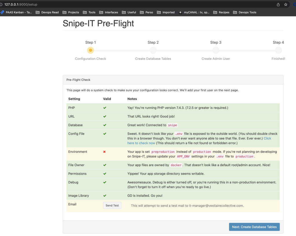
Use command kubectl-get, kubectl describe for have more information on the running apps.

https://kubernetes.io/docs/reference/generated/kubectl/kubectl-commands

Cloudflare Access and Argo tunnel configuration

Cloudflare Access and Argo tunnel configuration

Cloudflare Access replaces corporate VPNs with Cloudflare’s network. Instead of placing internal tools on a private network, customers deploy them in any environment, including hybrid or multi-cloud models, and secure them consistently with Cloudflare’s network. 

Cloudflare Access is one-half of the Cloudflare for Teams suite of products. 

In this article, we will see how to implement Cloudflare access and argo tunnel with an IDP from Cloudflare and Terraform.

For the example we chosen Okta as Idp, Okta is one of leader on the IAM technology. 

Argo Tunnel installation and configuration

In our case, we want to reach internal resources without a VPN. Argo tunnel will running directly from an internal server and will forward the traffic to the targeted resources. 

Install cloudflared on the server who running the argo tunnel. The package installer is available directly from https://github.com/cloudflare/cloudflared/releases

Once installed run the following command to login your cloudflared instance to your cloudflared tenant :

cloudflared tunnel login

Once installed run the following command to login to your cloudflared instance to your cloudflared tenant. Once validated Cloudflare will return a cert.pem who’s allowing you to create, delete tunnels and manage DNS records directly with cloudflared.

Run your first argo tunnel with the command : 

cloudflared tunnel create <NAME>

Once created you can list the argo tunnel created with the command :

cloudflared tunnel list 

You should have a list like that :

Argo tunnel configuration

At this step you have created your argo tunnel but you have to configure it.

Cloudflared tunnel will call a YAML config file to run , the config file is generally specfied in ~/.cloudflared, /etc/cloudflared or  /usr/local/etc/cloudflare

Config file should contain the tunnel id and the credential file generated with the command tunnel login.

Here an example of the config file :

tunnel: tunnel UUID 
credentials-file: /root/.cloudflared/tunneUUID.json
logfile: /var/log/cloudflared.log
hello-world: true
loglevel: debug
autoupdate-freq: 2h
 
ingress:
  - hostname: ssh.gitlab.domain.com
    service: ssh://localhost:22
  - hostname: web.gitlab.domain.com
    service: https://localhost:443
    # This "catch-all" rule doesn't have a hostname/path, so it matches everything
  - service: http_status:404

With this file the tunnel allows us to join the target through ssh and HTTPS with two different hostnames. 

Several flags are available for the config lets take a look to the present arguments : 

  • logfile → to log the tunnel ativities 
  • hello-world →  test server for validating the argo tunnel setup
  • loglevel → The verbosity levels of logs expected values trace, debug,  info, warn, error, fatal, panic
  • autoupdate-freq → the autoupdate freqency the default is 24h 

Ingress rules allow you to route the traffic from multiple hostname to multiple services through cloudflared and the argo tunnel. 

In the previous file, We will access my GitLab web interface through web.gitlab.domain.com and through ssh with ssh.gitlab.domain.com

A service for all rules is required at the last line, in this example, we use the http_status 404

Note that you can add the path to the hostname if you want. 

The list of supported protocols is available here

You can validate your configuration and ingress rules with the command : 

cloudflared tunnel ingress validate

 This command will verify if the ingress rules specified in the file are valid.

cloudflared tunnel ingress rule https://web.gitlab.domain.com

This command will test the url and check if associated rules exist.

Route DNS traffic

As we saw previously we will reach our target from the hostname through cloudflared. That means we have to route the traffic from the cloudflare records to the argo tunnel instance. 

We have two ways to do it lets take a look at these: 

Cloudflared Dashboard 

From the cloudflare dashboard select the DNS tab and add a new CNAME record. The record will point to the target tunelUUID.cfargotunnel.com, which is a domain available only through Cloudflare. 

Click save to register.

CLI

As you saw previously we can manage our Cloudflare record once we have logged cloudflared with the certificate.

To add the record simply use the following command : 

cloudflared tunnel route dns <UUID or NAME> web.gitlab.domain.com

Cloudflare Access configuration

Well at this step we have a working tunnel and DNS records to join internal applications. What we want to do is join the application through validation with our IDP and some policies like the below scheme.

Go to the >Cloudflare Teams dashboard and setup the IDP accordingly to this https://developers.cloudflare.com/cloudflare-one/identity/idp-integration

Note we will use Okta as IDP is in example.

Once the IDP added go to the Application Tab, click Add an application and select self-hosted

Enter an application name,  the hostname created on the cloudflared config, and select the Identity Provider.

Click on next to continue on the policy rule

Select the Rule Action Allow and include the Okta Groups → test 

This group is an existing group on our IDP.

Click next and Add application, you should have your created application like that : 

Cloudflare app launcher

Now Let’s configure the App Launcher, this portal contains a dashboard with the available  Cloudflare access app.

From Authentication select App Launcher and click Edit Access App Launcher.

Create a rule and add your IDP group :

You can rename your app launcher with the auth domain

Once configured connect on your app with the hostname you will be redirected to the app launcher.

Click on the IDP logo to sign in with.

Once logged from the IDP user will be redirected to the target.

To join the target through ssh user  have to install cloudflared on his computer and configure a config file on his computer accordingly to this: https://developers.cloudflare.com/cloudflare-one/applications/non-HTTP/ssh/ssh-connections#1-update-your-ssh-configuration-settings

Once configured connect with classic ssh from the computer to the hostname will redirect the user to the the app launcher  browser once the identity validated a token is returned to allow the connection through ssh. 

Cloudflare Access configuration from Terraform

Is possible to configure your Cloudflare access configuration directly from Terraform instead of the dashboard. 

You will find below an example for the configuration from Terraform :

terraform {
 required_providers {
   cloudflare = {
     source  = "cloudflare/cloudflare"
     version = "~> 2.0"
   }
# oauth Okta
resource "cloudflare_access_identity_provider" "okta_oauth" {
 account_id = "Cloudflare account id"
 name       = "Okta"
 type       = "okta"
 config {
   client_id     = "Client ID Okta app"
   client_secret = "secret Okta app"
   okta_account = "https://tenant.okta.com"
 }
}
 
resource "cloudflare_access_application" "gitlab_ssh" {
 zone_id                   = var.cloudflare_zone_id
 name                      = "Gitlab ssh"
 domain                    = "ssh.gitlab.domain.com"
 session_duration          = "24h"
 auto_redirect_to_identity = false
}
 
resource "cloudflare_access_application" "gitlab_web" {
 zone_id                   = var.cloudflare_zone_id
 name                      = "Gitlab web"
 domain                    = "web.gitlab.domain.com"
 session_duration          = "24h"
 auto_redirect_to_identity = false
}
 
 
resource "cloudflare_access_policy" "gitlab_ssh_policy" {
 application_id = cloudflare_access_application.gitlab_ssh.id
 zone_id        = "cloudflare zone id"
 name           = "gitlab ssh policy"
 precedence     = "1"
 decision       = "allow"
 
 include {
   okta {
     name                 = ["test"]
     identity_provider_id = cloudflare_access_identity_provider.okta_oauth.id
   }
 }
}
 
resource "cloudflare_access_policy" "gitlab_web_policy" {
 application_id = cloudflare_access_application.gitlab_web.id
 zone_id        = "cloudflare zone id"
 name           = "gitlab web policy"
 precedence     = "1"
 decision       = "allow"
 
 include {
   okta {
     name                 = ["test"]
     identity_provider_id = cloudflare_access_identity_provider.okta_oauth.id
   }
 }
}

In this previous example, the first block cloudflare_access_identity_provider allow the IDP configuration.

The blocks cloudflare_access_application define the application configuration, cloudflare_access_policy is for the policy configuration. 

Is possible to export the three blocks information with returned variable. 
Cloudflare terraform configuration guides are available from https://registry.terraform.io/providers/cloudflare/cloudflare/latest/docs.

Pritunl Zero installation and configuration

Install and config Pritunl Zero

Pritunl Zero is a zero trust system that provides secure authenticated access to internal services from untrusted networks without the use of a VPN.

Service can be ssh web in this article we will see how to implement pritunl zero in environment with docker and Traefik.

Pritunl Zero installation 

Our environment is a hosted web server with Traefik as proxy , Pritunl will be installed in a container with docker-compose.

Let’s take a look to the docker-compose file :

version: "3.7"
services:
 traefik:
    image: traefik
    restart: always
    ports:
      - "80:80"
      - "443:443"
    volumes:
      - "/var/run/docker.sock:/var/run/docker.sock:ro"
      - "./traefik/letsencrypt:/letsencrypt"
    command:
      - "--providers.docker=true"
      - "--providers.docker.exposedbydefault=false"
      - "--entrypoints.web.address=:80"
      - "--entrypoints.websecure.address=:443"
      - "--certificatesresolvers.mysmartserver.acme.dnschallenge=true"
      - "--certificatesresolvers.mysmartserver.acme.dnschallenge.provider=provider"
    environment:
      - "PROVIDER_ENDPOINT="
      - "PROVIDER_APPLICATION_KEY="
      - "PROVIDER_APPLICATION_SECRET="
      - "PROVIDER_CONSUMER_KEY="
 pritunl:
   image: "pritunl/pritunl-zero:latest"
   links:
     - pritunldb
   environment:
     - "MONGO_URI=mongodb://pritunldb:27017/pritunl-zero"
     - "NODE_ID=5b8e11e4610f990034635e98"
   ports:
     - '81:80'
     - '4444:4444'
     - '444:443'
 
   labels:
     - "traefik.enable=true"
     - "traefik.http.routers.traefikforward.tls.certresolver=mysmartserver"
     - "traefik.http.routers.pritunl.entrypoints=websecure,web"
     - "traefik.http.routers.pritunl.rule=Host(`zero.mysmartserver.com`)"
     - "traefik.http.routers.pritunl.rule=Host(`zero-users.mysmartserver.com`)"
 
 pritunldb:
   image: 'mongo'
   container_name: 'pritunldb'
   environment:
     - MONGO_INITDB_DATABASE="pritunl-zero"
     - MONGO_USER="mongo"
     - MONGO_PASS="password"
   ports:
     - '27017:27017'
   volumes:
     - mongo-data:/data/db
 
 
volumes:
 mongo-data:

The Traefik container listens on the HTTP and HTTPS ports of the server and also generates the SSL certificate with let’s encrypt.

In the environment section we set the dns provider information for let’s encrypt.

Pritunl should be available on the HTTP and HTTPS ports but they are already used with Traefik. 

We put these ports behind 81 and 444 the port 4444 is not required but we will use it later. 

The container is linked to a mongo db database where we create a pritunl-zero db, Node ID represents the instance pritunl zero.

The labels section is lanaged through traefik , we add 2 routes to join the server :

  • zero.mysmartserver.com
  • zero-users.mysmartserver.com

That mean we will  create two ssl ssl certificates for these two records.

Finally the pritunldb is hosted with a mongodb container available on the classic ports 27017.

We store the db to a volume  on the host.

Configure Web service with Pritunl Zero

Once the docker-compose up the pritunl instance is available on zero.pritunl.mysmartserver.com:444

Pritunl zero ask for login/password

Generate the password with the command pritunl-zero default-password for a docker connect on the instance with the command docker exec.

Connect on the interface and click on Certificates to set the certificates used through pritunl.

Note At this step your pritunl instance pushes an invalid certificate.

The purpose is to generate certificates for the admin console but also for service or user interface for ssh access. 

If you are using lets encrypt directly from traefik you can generate the certificates from acme.json and upload them to pritunl.

The jq command will help you to generate the certificates and the key :

 cat acme.json | jq -r ‘.[].Certificates[] | select(.domain.main== »‘zero.mysmartserver.com' ») | .certificate’ | base64 -d > zero.mysmartserver.com.crt

cat acme.json | jq -r ‘.[].Certificates[] | select(.domain.main== »‘zero.mysmartserver.com' ») | .key’ | base64 -d > zero.mysmartserver.com.key

Once the certificates and the key generated copy them on the instance.

Two options are available for certificate use let’s encrypt from pritunl or copy the certificate directly on the instance. 

For let’s encrypt your server will have  to be available from 80 and 443 ports.

Certificates text set will be available like this  :

The next step is to configure the node parameters 

Management is the pritunl admin console 

User is used if you want connect to ssh server from pritunl 

Proxy service allow you to join an internal HTTP/HTTPS ressources from the web

Bastion allows you to implement a layer to access your server from ssh.

It’s a secure way to access your server without VPN , it also allows you to add mfa for contextual response in a zero trust environment.

For the example we chose to set a proxy service to reach an internal resource from HTTP/HTTPS.

Enable Management and Proxy and enter the management Name.

For this example I changed the management port to 4444 to align it on the container port.

My server will be available to 4444 instead of 443 already used with traefik.

Add the generated certificate and save. 

You should reach your server to the 4444 ports on the management url

The generated certificates are correctly used on the server now

Go to the Services tab from the admin console and click on New

Indicate an external domain ( depending on your record but it’s not mandatory to indicate a host).

On the internal server indicate the internal resource you want to join , for example I add the container Ip and the port I want to reach.

Add a role and click on save.

Back to the Nodes tab select the service, add it and save your configuration.

Finally go to the Users tab and add a user with the same role created on the service

You  have to enter the same roles as the service to allow the user. 

The type user can be user from an IDP provider , IDP user can use the MFA (note SSO and MFA are not free on pritunl zero https://zero.pritunl.com/#pricing).

Once saved, go to the service external domain , you should land to a pritunl login page with the correct ssl certificate.

Connect the user previously created , you should be redirected to the server reached

Your internal service is now available from pritunl zero and internet. If you want to add policies or mfa rules you can create policies that you can assign to specific roles and services. 

The policy can help you to restrict the service to networks or add specific parameters to match for a service.

Zero Trust Approach

Zero trust approach

BYOD , Mobile user and device, cloud  are now a part of the IT landscape. 

Classic model security models viewed the network perimeter, often protected by firewalls and other on-prem solutions, as the ultimate line of defense. Users inside the enterprise network were considered trustworthy and given free rein to access company data and resources. Users outside the perimeter were considered untrustworthy and cannot access resources.

This concept is called the castle-and-moat concept. In castle-and-moat security, it is hard to obtain access from outside the network, but everyone inside the network is trusted by default. 

The problem with this approach is that once an attacker gains access to the network, they have free reign over everything inside.


Zero trust is a concept built to answer to that issue’s previous issues. Instead of having trustworthy people we will consider them. We will require identity verification for every person and device trying to reach our resources in the network. 

Zero trust components 

Zero trust is not a specific technology , it is more a concept or approach. That means we can build zero trust from many ways but the tools have mainly the same functions. 

As said previously zero trust require strong identity verification , so IAM is one of the main components. IAM (Identity and access management) is a way to tell who users are and what they are allowed to do. 

Identity management (IdM), also known as identity and access management (IAM or IdAM), is a framework of policies and technologies for ensuring that the proper people in an enterprise have the appropriate access to technology resources.

You can implement MFA (multi factor authentication) in addition to a password with an IAM , but also tracking access into the Company.

IAM helps prevent identity-based attacks and data breaches that come from privilege escalations (when an unauthorised user has too much access).

MFA which require more than one piece of information to authenticate a user , is a core value of the Zero trust. 

The IAM policies are built on user context (Who are they? Are they in a risky user group?)  and application context (which application the user is trying to access). 

It is important to use microsegmentation (is a method of creating zones in data centers and cloud environments to isolate workloads from one another and secure them individually). 

Organizations use microsegmentation to reduce the network attack surface, improve breach containment and strengthen regulatory compliance.

Zero trust system will need to monitor the location context ( Where the user is logged , analyse impossible travel , check new city /state/country).

Device context is a strict control on device access ( Is it a new device ?, Is it a managed device). MDM can help you to push a strong and efficient device context policy.

For example you can require a computer  enrolled (from byod or zero touch) and compliant on your MDM to access the application. 

Once these contexts are verified you will push a contextual response ( allow access , Require mfa or block access).

Build a zero trust system 

From an existing and classical infrastructure you will start the zero trust implementation from an audit of your existing resources. 

Analyse which applications can be moved to a cloud model (eg : classical file server , laptop identity). 

You can use some tools to redirect ports from an https target with tools like Pritunl Zero , Okta gateway server , Cloudflare access or Azure application proxy for example.

Improve or implement IAM to your identities system with an IDP ( eg : Google , Azure , Okta, Fusion auth).

Once the IAM is implemented , is it important to create policy access and build the application and user context as read previously.

Mainly to build a zero trust policiy you can use tools like proxy , it allow you access to the product securely with https but also redirect from a secure point.

example of how Cloudflare Access work with IDP

Build a device policy with a mdm system (mobile device management), for company devices and BYOD devices (Mosyle , Intune , Jamf , Workspace one). 

Several IDPs( Okta , Azure or Google)  can already communicate with the MDM systems.

Okta fast pass is linked to the mdm and can check registered devices

NOTE : For Azure the communication with the mdm is done with Intune and based on the conditional access.

Intune device can be verified in a conditional access policy

Conclusion 

Well with this article we have seen what are the global components of the Zero trust approach. We’ve also seen how we can consider moving our infrastructure to zero trust. 

For the next articles we will try to go deeper with concrete examples of zero trust implementation.

Aws application load balancer and Okta Oidc

Aws application load balancer and Okta Oidc

In this article we will see how to add Okta authentication behind the Aws load balancer with Terraform.

Create the Okta Application

From Okta → Applications click on the Add Application and then Create New App

Select the Platform Web and OpenID Connect for Sign on method and click on Create

Once created you landing on the OpenId integration page

Name your application 

The login redirect should be your DNS Record/oauth2/v1/authorize

lets say the record here is myrecord.okta.com

Once saved you will be on the App configuration page.

Let’s see some settings. 

The grant type should be Authorization Code that means the code is returned from the Authorization Endpoint and all tokens are returned from the Token Endpoint.

Login redirect URIs →  should be https://DNS/oauth2/idpresponse more information on https://docs.aws.amazon.com/elasticloadbalancing/latest/application/listener-authenticate-users.html

Logout redirect URIs → Can be your Okta tenant or whatever you want

Login initiated by → App Only 

Initiated Login URI  → You can directly put your application url to launch it directly from Okta

In the Client Credentials part  you will find two importants informations that are used on the Load Balancer. 

Client ID ⇒  The application identifier used on the header 

Client secret  ⇒ The secret is used to exchange the authorization code 

Terraform configuration 

Now we have our Okta application configured and we have to write our Aws configuration. 

Firstly we create the Load Balancer follow the terraform doc about it : https://registry.terraform.io/providers/hashicorp/aws/latest/docs/resources/lb

resource "aws_lb" "alb_test" {
 name               = "alb_test"
 subnets            = aws_subnet.public.*.id
 internal           = false
 load_balancer_type = "application"
 security_groups    = [aws_security_group.lb_sg.id]
 
 tags = {
   Name     = "alb_test"
   Project  = "production"
 }
}

Once the Load balancer is created we can create the target group that we will reach. 

Resource "aws_lb_target_group" "test_tg" {
 name     = "test_tg"
 port     = 80
 protocol = "HTTP"
 vpc_id   = module.core.main.id
}
 
resource "aws_lb_target_group_attachment" "test_tga" {
 target_group_arn = aws_lb_target_group.alb_test.arn
 target_id        = aws_instance.your_ec2_instance.id
 port             = 80
}

We can now create our Listener settings.

Remind A listener is a process that checks for connection requests, using the protocol and port that you configure. The rules that you define for a listener determine how the load balancer routes requests to its registered targets.

Firstly we create a listener on the http port and we redirect it on https 

resource "aws_lb_listener" "lb_l_80" {
 load_balancer_arn = aws_lb.alb_test.arn
 port              = "80"
 protocol          = "HTTP"
 
 default_action {
   // redirect to https
   type = "redirect"
 
   redirect {
     port        = "443"
     protocol    = "HTTPS"
     status_code = "HTTP_301"
   }
 }
}

The listener http is redirected to the https listener that we will create

resource "aws_lb_listener" "lb_443" {
 load_balancer_arn = aws_lb.alb_test.arn
 port              = "443"
 protocol          = "HTTPS"
 ssl_policy        = "ELBSecurityPolicy-2016-08"
 certificate_arn   = var.alb_certificate_arn

Well now is time to create the default action remember the default action acting on default when we contact the Load balancer.

default_action {
   type = "authenticate-oidc"
   authenticate_oidc {
     authorization_endpoint = "https://myrecord.okta.com/oauth2/v1/authorize"
     client_id              = 0oa6d4cqxdDaSPkTO357
     client_secret          = wYfvk4_DW_dBtnMTvf2Gv22EC0-Qhn6wDEBWHswn
     issuer                 = "https://myrecord.okta.com"
     token_endpoint         = "https://myrecord.okta.com/oauth2/v1/token"
     user_info_endpoint     = "https://myrecord.okta.com/oauth2/v1/userinfo"
     session_cookie_name        = "AWSELBAuthSessionCookie"
     session_timeout            = "300"
     scope                      = "openid profile"
     on_unauthenticated_request = "authenticate"
   }
 }
 default_action {
   type             = "forward"
   target_group_arn = aws_lb_target_group.test_tg.arn
 }
}

We can take a look what is done on aws :

We have now finished when we will join the loadbalancer we will redirected to Okta. You can add some spécifics rules. Do note hesitate read more on https://registry.terraform.io/providers/hashicorp/aws/latest/docs/resources/lb_listener_rule You are not limited on Okta Apps so you can create as many applications as rules on the loadbalancer.

Note If you note allowed to the application you will be have a 401 returned.

Thank you for reading !

Synchronise Snipe IT and Mosyle through API

Synchronise Snipe IT and Mosyle through API

Mosyle is a beautiful MDM provider and less expensive alternative to Jamf. This present a Python script whos track modification on the assets and assign it to the enrolled user. You can find the whole script on https://github.com/dem972/Mosyle_2snipe

# Import all the things
import json
import datetime
import configparser

from mosyle import Mosyle
from snipe import Snipe

# Converts datetime to timestamp for Mosyle
ts = datetime.datetime.now().timestamp() - 200

# Set some Variables from the settings.conf:
config = configparser.ConfigParser()
config.read('settings.ini')

# This is the address, cname, or FQDN for your snipe-it instance.
apiKey = config['snipe-it']['apiKey']
defaultStatus = config['snipe-it']['defaultStatus']
apple_manufacturer_id = config['snipe-it']['manufacturer_id']

# Set the token for the Mosyle Api
mosyle = Mosyle(config['mosyle']['token'])

# Set the call type for Mosyle
calltype = config['mosyle']['calltype']

mosyle_response = mosyle.list().json()
mosyle_test = mosyle.list()
if calltype == "timestamp":
    mosyle_response = mosyle.listTimestamp(ts, ts).json()


# Set the token for Snipe It
snipe = Snipe(apiKey)


# Return Mosyle hardware and search them in snipe
for sn in mosyle_response['response'][0]['devices']:
   
    asset = snipe.listHardware(sn['serial_number']).json()
    model = snipe.searchModel(sn['device_model']).json()

    print(sn['device_model'])

    if sn['CurrentConsoleManagedUser'] != None and "userid" in sn:
        mosyle_user = sn['userid']

    else:
        continue

    
    print("Mosyle devices found:", sn['serial_number'],sn['device_name'], sn['device_model'])

    if mosyle_response['response'] == "status":
        exit(1)

    
    # Create the asset model if is not exist
    if model['total'] == 0:
        if sn['os'] == "mac":
            model = snipe.createModel(sn['device_model']).json()
            model = model['payload']['id']
        if sn['os'] == "ios":
            model = snipe.createMobileModel(sn['device_model']).json()
            model = model['payload']['id']

    else:
        model = model['rows'][0]['id']

    # If asset doesnt exist create and assign it
    if asset['total'] == 0:
        asset = snipe.createAsset(sn['device_name'], model, sn['serial_number']).json()
        if mosyle_user == "users":
            snipe.assignAsset(mosyle_user['response'][0]['users'][0]['identifier'], asset['payload']['id'])
        continue

    # Update existing Devices

    if asset['total'] == 1:
        #f"{x:.2f}"
        print(asset['rows'][0]['name'])
        snipe.updateAsset(asset['rows'][0]['id'], sn['device_name'], sn['wifi_mac_address'], str(float(sn['available_disk'])), sn['osversion'], str(float(sn['total_disk'])))

    # Check the asset assignement state

    if asset['rows'][0]['assigned_to'] == None and sn['userid'] != None:
            snipe.assignAsset(sn['userid'], asset['rows'][0]['id'])
            continue

    elif sn['userid'] == None:
        snipe.unasigneAsset(asset['rows'][0]['id'])
        continue

    elif asset['rows'][0]['assigned_to']['username'] == sn['userid']:
        continue

    elif asset['rows'][0]['assigned_to']['username'] != sn['userid']:
        snipe.unasigneAsset(asset['rows'][0]['id'])
        snipe.assignAsset(sn['userid'], asset['rows'][0]['id'])

Snipe It Docker-Compose deployment

Snipe It Docker-Compose deployment

Snipe IT is a lovely Free Open Source (FOSS) project built on Laravel 5.7. Snipe It easily allows you manage your It parc with a powerful api.

Let’s take a look about the docker-compose yml file.

version: '3.7'
services:
  snipe:
    image: snipe/snipe-it:latest
    ports:
      - 8000:80
    env_file: ./snipe/env-file
    volumes:
      - './data:/var/lib/snipeit'
    links:
      - snipedb:snipedb
      - redis
  snipedb:
    image: mysql:5.6
    env_file: ./snipe/.env

Nb : we used a mysql:5.6 but for the latest version of snipe it you can also use maria db.

Env-file contain all the parameters you need to configure the DB and your snipe It option you will find below an example:

Env File Parameters

 #Mysql Parameters
 MYSQL_ROOT_PASSWORD = awesomepassword
 MYSQL_DATABASE = snipe
 MYSQL_USER = snipeit
 MYSQL_PASSWORD = awesomepassword

 # Email Parameters
 # - the hostname/IP address of your mailserver
 MAIL_PORT_587_TCP_ADDR=smtp server 
 #the port for the mailserver (probably 587, could be another)
 MAIL_PORT_587_TCP_PORT=587
 # the default from address, and from name for emails
 MAIL_ENV_FROM_ADDR=yourmail@domain.com
 MAIL_ENV_FROM_NAME= Snipe Alerting
 # - pick 'tls' for SMTP-over-SSL, 'tcp' for unencrypted
 MAIL_ENV_ENCRYPTION=tls
 # SMTP username and password
 MAIL_ENV_USERNAME=your mail login
 MAIL_ENV_PASSWORD= your mail password


 # Snipe-IT Settings
 APP_ENV=production
 APP_DEBUG=false
 APP_KEY=base64:
 APP_URL=url of your snipe it 
 APP_TIMEZONE=Europe/Paris
 APP_LOCALE=en
 DB_CONNECTION=mysql
 DB_HOST=snipedb
 DB_DATABASE=snipe
 DB_USERNAME=snipeit
 DB_PASSWORD=awesomepassword
 DB_PORT=3306